This guide provides a step-by-step tutorial on creating a custom OBD2 to C-Type USB cable for vehicle diagnostics. Disclaimer: This is a DIY project, proceed with caution and at your own risk. I am not responsible for any damages or issues that may arise.
Understanding the OBD2 Connector and Required Parts
Before starting, it’s crucial to understand that a direct OBD2 to C-Type USB connection isn’t possible without an interface device. Standard OBD2 connectors use a 16-pin J1962 connector, while USB utilizes a different communication protocol. This guide details building a harness to connect an OBD2 cable to a 4-pin connector, which can then connect to a separate USB interface device (not covered in this guide).
Parts and Tools:
- 4-Pin Connector: Choose a connector with pin/wire sizes compatible with 22-16 AWG and insulation/seal sizes of 1.3-1.7mm. (Example)
- OBD-II Cable: A standard OBD2 cable (female connector). (Example)
- Wire Strippers/Cutters: For preparing the wires.
- Needle-Nose Pliers: For precise handling of wires and pins.
- Soldering Iron (Recommended): For securing wire connections.
- Molex Crimping Tool (Optional): For crimping the connector pins.
- Zip Ties: For organizing wires.
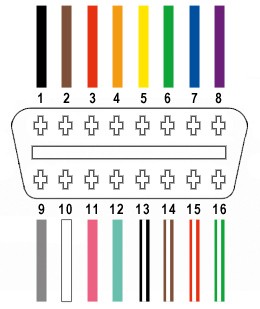
OBD2 Pin Configuration:
Only four wires from the OBD2 connector are needed for this project:
- Pin 4: Chassis Ground (Orange Wire)
- Pin 6: CAN High (J-2234) (Green Wire)
- Pin 14: CAN Low (J-2234) (Brown with White Stripe Wire)
- Pin 16: Battery Power (Green with White Stripe Wire)
Building the OBD2 to 4-Pin Harness
Step 1: Prepare the OBD2 Cable
Remove the outer sheath and shielding from the OBD2 cable. Separate the four necessary wires (pins 4, 6, 14, and 16) and use zip ties to secure the remaining wires.
Step 2: Prepare the Wires for the 4-Pin Connector
Strip approximately 3/8″ of insulation from each of the four wires. If the wire gauge is smaller than the 4-pin connector’s pin size (as in this example with 26AWG wire and 22AWG pins), fold and twist the exposed wire to increase its thickness. Slide a rubber seal onto each wire.
Step 3: Connect the Wires to the 4-Pin Connector Pins
Insert the exposed wire into the front prongs of the 4-pin connector pin. Use needle-nose pliers to hold the wire in place if necessary.
Step 4: Secure the Wire Connection
Solder the wire to the pin for a secure connection. Alternatively, if you have a Molex crimping tool, crimp the connector prongs over the wire.
Step 5: Secure the Rubber Seal
Slide the rubber seal up to the back prongs of the connector pin and crimp or use pliers to fold the prongs over the seal.
Step 6: Twist Wire Pairs
Pair and twist the following wires together:
- Pin 4 (Orange) with Pin 16 (Green/White)
- Pin 6 (Green) with Pin 14 (Brown/White)
Step 7: Insert Pins into the 4-Pin Connector Housing
Insert the pins into the 4-pin connector housing in the following order:
- Slot A: Pin 14 (Brown/White)
- Slot B: Pin 6 (Green)
- Slot C: Pin 16 (Green/White)
- Slot D: Pin 4 (Orange)
Ensure each pin clicks into place. Use needle-nose pliers to assist if needed.
Final Assembly and Testing
Connect the finished harness to your OBD2 port and the corresponding USB interface device. You can then use diagnostic software to communicate with your vehicle’s ECU.
This image demonstrates a successful connection and data retrieval using the custom harness. Remember, this harness needs to be connected to a compatible USB interface device to function.