Connecting an Arduino Obd2 Shield to a vehicle’s OBD-II port can be challenging. This article addresses common issues encountered when using a Seeed CAN shield V2.0 with an Arduino to retrieve vehicle data, specifically focusing on obtaining engine RPM and speed. We will explore potential problems, troubleshooting steps, and code examples to help you establish a successful connection and retrieve the data you need.
Understanding the Challenge of OBD-II Communication with Arduino
The OBD-II protocol utilizes the CAN (Controller Area Network) bus for communication. While seemingly straightforward, establishing reliable communication between an Arduino OBD2 shield and a vehicle’s ECU (Engine Control Unit) can be complex. Issues can arise from incorrect wiring, improper CAN bus settings, faulty hardware, or errors in the code used to request and interpret data.
Common Issues and Troubleshooting Steps
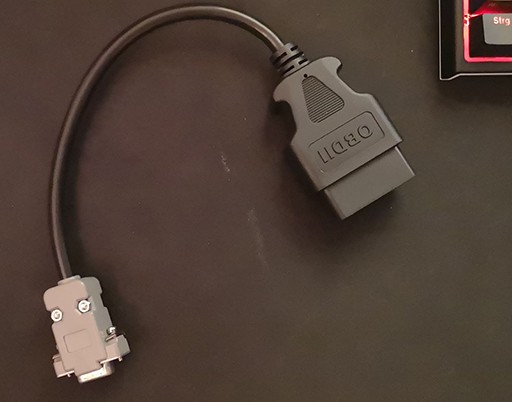
One common problem is continuous spamming of messages by the OBD2 shield without receiving a response from the vehicle. This could indicate an issue with the shield itself, incorrect message formatting, or a lack of proper initialization of the CAN bus. Verifying the OBD2 to DB9 cable connection using a multimeter is crucial. Ensuring the correct CAN bus speed (typically 500kbps for OBD-II) is also essential.
Another issue is the lack of response from the vehicle’s ECU even after sending valid OBD-II PID (Parameter ID) requests. This might stem from incompatibility between the shield and the vehicle’s specific CAN protocol implementation, incorrect PID requests, or the vehicle’s ECU not supporting the requested PIDs. Consulting the vehicle’s documentation for supported PIDs is recommended.
Analyzing the Code Examples
The provided code examples demonstrate attempts to request engine RPM (PID 0x0C) and vehicle speed (PID 0x0D). However, several potential issues exist:
- Incorrect Message Formatting: The OBD-II request message requires specific formatting, including the correct number of data bytes and proper placement of the PID.
- Lack of Error Handling: The code lacks robust error handling to identify and address potential communication failures.
- Improper CAN Bus Initialization: The CAN bus initialization might not be correctly configured for the specific OBD-II requirements of the vehicle.
Recommendations for Successful Data Retrieval
To improve the chances of successful data retrieval:
- Verify Hardware: Double-check all connections and ensure the OBD2 shield and Arduino are functioning correctly. Consider testing the shield with a known working OBD-II simulator.
- Validate CAN Bus Settings: Confirm that the CAN bus speed and other settings match the vehicle’s requirements.
- Refine Code: Implement robust error handling and ensure the OBD-II request messages are correctly formatted according to the standard. Utilize libraries specifically designed for OBD-II communication to simplify the process.
- Consult Vehicle Documentation: Refer to the vehicle’s specific OBD-II documentation to identify supported PIDs and any specific communication requirements.
Conclusion
Successfully using an Arduino OBD2 shield requires careful attention to detail in both hardware and software. By addressing potential issues with wiring, CAN bus settings, code implementation, and consulting vehicle-specific documentation, you can overcome challenges and achieve reliable data retrieval for your automotive projects. Remember to thoroughly test your setup and code to ensure accurate and consistent communication with the vehicle’s ECU.