Looking for a clear explanation of OBD2 and its connector pins? This guide provides a practical introduction to On-Board Diagnostics (OBD2), including the OBD2 connector pinout, Parameter IDs (PIDs), and the relationship to CAN bus. You’ll learn how to request and decode OBD2 data, understand key logging use cases, and gain valuable practical tips.
What is OBD2?
OBD2 is a standardized system that allows access to diagnostic trouble codes (DTCs) and real-time vehicle data through a connector. It’s your car’s built-in self-diagnostic system. When your dashboard’s malfunction indicator light illuminates, it signals an issue detectable by an OBD2 scanner connected to the OBD2 16 pin connector. This scanner sends requests and receives responses containing crucial data like speed, fuel level, and DTCs for troubleshooting.
OBD2 Connector Pinout: Decoding the Connection
The standardized OBD2 connector, defined by SAE J1962/ISO 15031-3, provides a consistent interface for accessing vehicle data. This 16-pin connector, often located near the steering wheel, facilitates communication between the vehicle’s systems and diagnostic tools.
Key aspects of the OBD2 connector pinout include:
- Pin 16: Supplies constant battery power, even with the ignition off.
- Pin 6 & Pin 14: Designated for CAN-H and CAN-L signals respectively, reflecting the common use of CAN bus as the underlying communication protocol.
- Protocol Dependence: The specific pin usage can vary depending on the communication protocol employed by the vehicle.
Type A vs. Type B Connectors:
While Type A connectors are common in cars, Type B connectors are often found in heavier vehicles. Key differences include voltage output (12V for Type A, 24V for Type B) and a distinctive interrupted groove in the Type B connector.
OBD2 and CAN Bus: The Language of Modern Vehicles
Since 2008, ISO 15765 has mandated CAN bus as the primary communication protocol for OBD2 in US vehicles. This standard defines specific parameters for communication, including bit-rates (250K or 500K), CAN identifiers (11-bit or 29-bit), and data frame structure. OBD2 utilizes specific CAN IDs for requests (e.g., 0x7DF for functional addressing) and responses (e.g., 0x7E8 from the Engine Control Module).
Decoding OBD2 Data: Understanding PIDs and Modes
OBD2 data is transmitted using ISO-TP (ISO 15765-2), allowing for payloads exceeding the standard 8-byte CAN frame limit. Within each message, Mode and Parameter IDs (PIDs) specify the requested data.
- Modes: Ten standardized diagnostic services (modes) exist, with Mode 0x01 providing real-time data.
- PIDs: Each mode contains numerous PIDs, each corresponding to a specific data parameter (e.g., vehicle speed, RPM). Mode 0x01 PID 0x00 is mandatory for emissions-related ECUs and indicates supported PIDs.
Practical OBD2 Data Logging: Tools and Techniques
Tools like the CANedge data logger enable recording and decoding OBD2 data. By configuring specific PID requests, filtering responses, and utilizing DBC files for decoding, valuable insights can be extracted.
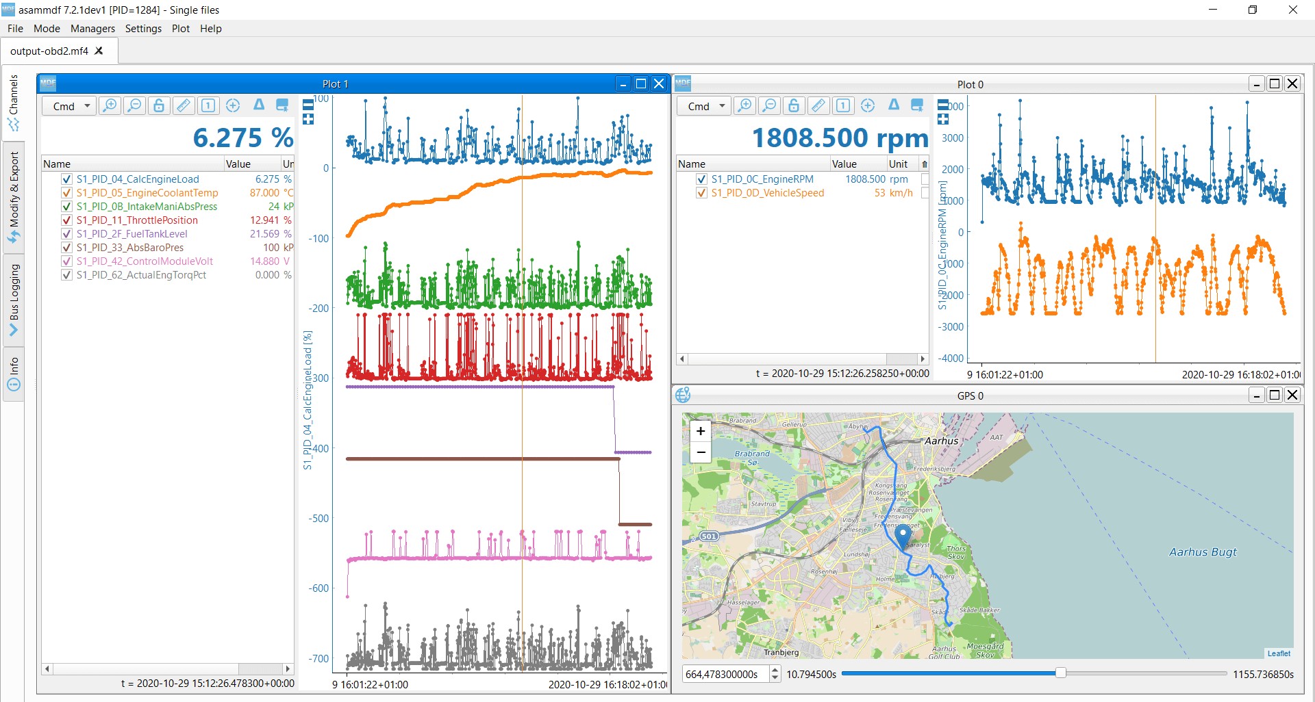 Example of OBD2 data logging and decoding using asammdf
Conclusion: Harnessing the Power of OBD2 Pins
Understanding the OBD2 pinout and associated protocols opens a wealth of information about vehicle performance and diagnostics. From simple code reading to complex data analysis, the OBD2 system provides crucial insights for mechanics, enthusiasts, and fleet managers alike. Leveraging the right tools and knowledge empowers users to unlock the full potential of OBD2 data. Contact us today to explore how our OBD2 data logging solutions can meet your needs.
CANedge product image