Connecting a Yamaha diagnostic connector with a 4-pin interface to a standard OBD2 diagnostic tool can be a challenge. This guide provides a step-by-step approach to building your own adapter, allowing you to access your Yamaha’s diagnostic data using readily available OBD2 tools. This process involves specific wiring configurations and requires basic electrical skills and tools.
Understanding the Yamaha 4-Pin Connector and OBD2
Yamaha uses a unique 4-pin connector for diagnostics on many of its motorcycles, ATVs, and other powersport vehicles. This connector differs significantly from the standardized 16-pin OBD2 connector found in most cars and trucks. To bridge this gap, a custom adapter is required. This adapter will map the necessary signals from the Yamaha 4-pin connector to the corresponding pins on an OBD2 connector, enabling communication with a standard OBD2 diagnostic tool.
Building the Yamaha 4-Pin to OBD2 Adapter
This DIY adapter requires basic tools like wire strippers, needle-nose pliers, and optionally, a soldering iron and a Molex crimping tool. You’ll also need a 4-pin connector (compatible with 22-16AWG wire and 1.3-1.7mm insulation) and an OBD2 cable or connector.
Wiring Configuration:
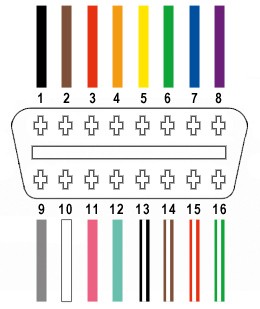
Only four wires from the OBD2 connector’s 16 pins are needed:
- OBD2 Pin 4 (Chassis Ground): Connect to the corresponding ground pin on the Yamaha 4-pin connector (usually black).
- OBD2 Pin 6 (CAN High): Connect to the CAN High pin on the Yamaha 4-pin connector.
- OBD2 Pin 14 (CAN Low): Connect to the CAN Low pin on the Yamaha 4-pin connector.
- OBD2 Pin 16 (Battery Power): Connect to the battery positive pin on the Yamaha 4-pin connector (usually red).
Step-by-Step Instructions:
- Prepare the Wires: Strip the outer sheath and shielding from the OBD2 cable, separating the four necessary wires (orange, green, brown/white, and green/white). Secure the remaining wires with a zip tie. Twisting the wire pairs (orange/green-white and green/brown-white) is recommended.
- Prepare the 4-Pin Connector Pins: If the OBD2 wires are thinner than the 4-pin connector pins (e.g., 26AWG vs. 22AWG), fold and twist the exposed wire to increase its thickness. Slide a rubber seal onto each wire before inserting it into the pin.
- Connect the Wires to the Pins: Insert the exposed wire into the front prongs of the 4-pin connector pin. Solder or crimp the connection to secure the wire.
- Secure the Seal: Slide the rubber seal up to the back prongs of the pin and crimp them over the seal to provide a weathertight connection.
- Assemble the 4-Pin Connector: Insert the pins into the 4-pin connector housing according to the Yamaha pinout diagram (if available). Ensure each pin clicks into place. A common orientation is: Brown/White (Pin 14) in slot A, Green (Pin 6) in slot B, Green/White (Pin 16) in slot C, and Orange (Pin 4) in slot D.
- Test the Adapter: Connect the adapter to the Yamaha diagnostic connector and an OBD2 diagnostic tool. Attempt to read diagnostic codes or data to verify functionality.
Conclusion
Building a Yamaha Diagnostic Connector 4 Pin To Obd2 adapter can be a cost-effective solution for accessing your vehicle’s diagnostic information. This guide provides a general framework. Always consult your Yamaha service manual for specific wiring diagrams and connector pinouts to ensure compatibility and prevent damage to your vehicle’s electrical system. This project involves working with electrical components, so proceed with caution and consult a professional if you are unsure about any step.