This guide provides a step-by-step walkthrough on how to create a custom wiring harness for connecting a SEAL car adapter to an OBD2 scanner. This setup is particularly useful for diagnostics and programming on vehicles requiring a specific 4-pin connector. While this guide is based on personal experience and not professional advice, it aims to offer a clear and detailed approach to building your own adapter. Proceed at your own risk and consult a professional if you have any doubts.
Gathering Your Tools and Parts
Before you begin, ensure you have the following tools and parts:
- Tools:
- Wire strippers/cutters
- Needle-nose pliers
- Soldering iron (highly recommended)
- Molex crimping tool (optional but recommended)
- Parts:
- 4-pin connector (22-16 AWG pin/wire size, 1.3-1.7mm insulation/seal size) – Example Part
- OBD-II Cable (Female Connector) – Example Part
You can potentially save money if you have spare 22-16 AWG wire. If so, purchase only the female OBD-II connector and the 4-pin connector. Knowing the exact gauge of your wire is crucial for selecting the correct 4-pin connector.
Identifying the Necessary OBD2 Pins
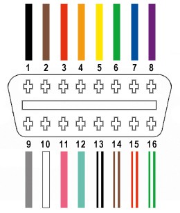
A standard OBD2 connector (OBD2C) has 16 pins. For this SEAL car adapter, you’ll only need four:
- Pin 4: Chassis Ground (Orange wire)
- Pin 6: CAN (J-2234) High (Green wire)
- Pin 14: CAN (J-2234) Low (Brown with white stripe wire)
- Pin 16: Battery Power (Green with white stripe wire)
Building the Harness: A Step-by-Step Guide
Step 1: Preparing the OBD2 Cable
Remove the outer sheath and shielding from the OBD2C. Separate the four necessary wires (orange, green, brown/white, green/white) and secure the remaining wires with a zip tie to prevent interference.
Step 2: Preparing the Wires for the 4-Pin Connector
Strip approximately 3/8″ of insulation from each of the four wires. If using 26AWG wire from the OBD2 cable with a 4-pin connector designed for 22AWG, double the wire over and twist it to increase thickness for a secure fit in the pin connector. Slide a rubber seal (included with the 4-pin connector kit) over each wire.
Step 3: Connecting the Wires to the 4-Pin Connector Pins
Insert the exposed wire into the front prongs of the 4-pin connector pin. You might need needle-nose pliers to hold the thin wire in place.
Step 4: Securing the Connection (Soldering or Crimping)
-
Soldering: Solder the wire to the pin for a solid connection. This is highly recommended, especially with thinner wires.
-
Crimping: If you have a Molex crimping tool, crimp the connector prongs over the wire. If not, carefully use needle-nose pliers to fold the prongs over the wire and then crush them down for a secure hold.
Step 5: Securing the Seal
Slide the rubber seal up to the back prongs of the connector pin and fold the prongs over the seal using the same method as Step 4.
Step 6: Twisting Wire Pairs
Pair and twist the following wires together:
- Orange (Pin 4) and Green/White (Pin 16)
- Green (Pin 6) and Brown/White (Pin 14)
Step 7: Connecting Pins to the 4-Pin Connector Housing
Insert the pins into the 4-pin connector housing (4PC) in the following order:
- Slot A: Brown/White (Pin 14)
- Slot B: Green (Pin 6)
- Slot C: Green/White (Pin 16)
- Slot D: Orange (Pin 4)
Insert each pin from the back of the connector and use needle-nose pliers to pull it through until you hear a click, indicating it’s locked in place.
Final Product and Testing
Your completed SEAL car adapter should look like this:
Test the adapter by connecting it to your vehicle’s diagnostic port and your OBD2 scanner. Confirm functionality by reading and clearing diagnostic trouble codes.