The SparkFun CAN-BUS Shield empowers your Arduino projects with vehicle data access through the OBD-II port. This comprehensive guide provides a step-by-step approach to connecting your Arduino to a vehicle’s CAN-BUS network using the SparkFun OBD-II UART and CAN-BUS Shield. We’ll cover hardware requirements, connections, library installation, and example code to get you started with reading vehicle data.
Understanding the Hardware
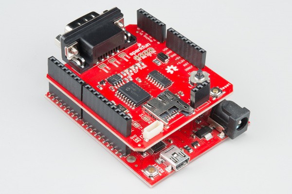
The SparkFun CAN-BUS Shield features a DB9 connector for interfacing with OBD-II ports via a DB9 to OBD-II cable. It also includes a GPS connector, an LCD connector for displaying data, a joystick for user input, a microSD slot for data logging, and several jumpers for configuration. Key components include:
- DB9 Connector: Connects to the OBD-II port using a DB9 to OBD-II cable.
- MCP2515 CAN Controller: Handles CAN communication.
- MCP2551 CAN Transceiver: Provides physical interface to the CAN bus.
- Jumpers: Configure DB9 pin settings for compatibility with different OBD-II cables.
Hardware Hookup
- Solder Headers: Solder stackable headers to the CAN-BUS Shield. If using an LCD, solder the appropriate connector.
- Connect to Arduino: Attach the shield to your Arduino board.
- Connect Peripherals (Optional): Connect GPS module, LCD screen, and a formatted microSD card if needed. Ensure the GPS has a clear view of the sky for optimal performance. Consider a GPS extension cable if using an enclosure.
- Connect to OBD-II: Connect the DB9 connector on the shield to the OBD-II port of your vehicle using a DB9 to OBD-II cable.
Arduino Library Installation
Install the SparkFun CAN-BUS Arduino Library through the Arduino Library Manager by searching for “SparkFun CAN-BUS.” Alternatively, download the library from the GitHub repository and manually install it. This library simplifies interaction with the CAN-BUS Shield.
Example: Reading Engine RPM
The following code snippet demonstrates how to request and read engine RPM data from a vehicle’s ECU. This example utilizes the ecu_req function from the SparkFun CAN-BUS library.
#include <Canbus.h>

// ... other code ...

char *EngineRPM;
char buffer[64];

void loop() {
  // ... other code ...

  Canbus.ecu_req(ENGINE_RPM, buffer);
  EngineRPM = buffer;

  // ... process EngineRPM data ...
}
This code sends a request for the engine RPM parameter ID (PID) and stores the received data in the buffer. Remember to consult your vehicle’s documentation for specific PIDs.
Troubleshooting and Considerations
- Vehicle Compatibility: Ensure your vehicle and its OBD-II system support CAN communication and the specific PID you are trying to access.
- Protocol: Verify that the CAN-BUS shield is compatible with your vehicle’s OBD-II communication protocol.
- PID Accuracy: The accuracy of the received data depends on the vehicle’s ECU and sensor implementations.
- Power Supply: The shield and Arduino can be powered via the OBD-II port or an external power supply.
Conclusion
By following this guide, you can successfully connect your Arduino to a vehicle’s CAN-BUS network using the SparkFun OBD2 UART and CAN-BUS Shield. This opens up a wide range of possibilities for automotive projects, from data logging and diagnostics to custom dashboards and interactive vehicle applications. Remember to consult the SparkFun CAN-BUS library documentation and your vehicle’s specifications for more advanced functionalities and specific PIDs.