Connecting a modern OBD2 scanner to a pre-1996 Chrysler vehicle with a 6-pin OBD1 system requires understanding the wiring configurations. This guide provides a detailed walkthrough of the process, addressing potential challenges and offering solutions for successful communication.
Understanding Chrysler’s OBD1 System
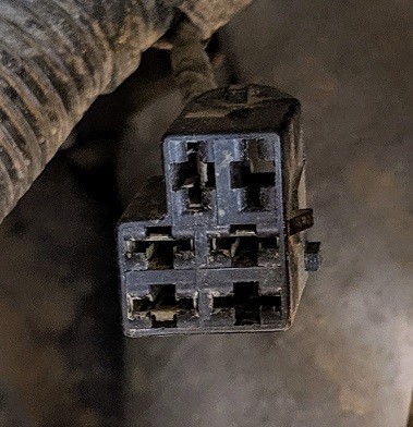
Chrysler vehicles manufactured before 1996 utilize a unique 6-pin connector for diagnostics, located under the hood. This connector provides access to the engine controller’s SCI-bus (Serial Communications Interface). Key pins include:
- Pin 1/2: +12V (not always present)
- Pin 3: PCM-TX (Powertrain Control Module Transmit)
- Pin 4: GND (Ground)
- Pin 6: PCM-RX (Powertrain Control Module Receive)
Before connecting any diagnostic equipment, it’s crucial to verify the voltages on the SCI-RX and SCI-TX pins. With no scanner connected, SCI-RX (Pin 6) to GND (Pin 4) should measure 5 volts, while SCI-TX (Pin 3) to GND (Pin 4) should read 0 volts. The SCI-TX voltage should rise to 5 volts when communication with the scan tool begins.
Addressing Inverted UART Logic
Some older Chrysler models may employ inverted UART (Universal Asynchronous Receiver/Transmitter) logic in the 6-pin connector. This requires a logic inverter circuit between the engine connector and the OBD2 scanner, as most scanners only accept non-inverted UART signals. A 74LS04 logic inverter IC, along with a 100 nF decoupling capacitor and a +5V power supply (sourced from the scanner), can effectively address this issue.
Chrysler 6 Pin to OBD2 Adapter: Challenges and Solutions
While commercially available “Chrysler 6 Pin OBD1 to OBD2” adapters exist, they often present wiring inconsistencies:
-
Grounding Issues: OBD1 Pin 4 (ground) might connect solely to OBD2 Pin 5 (signal ground) on some adapters, preventing the scanner from grounding correctly. Ensure your scanner has a selectable ground jumper and is independently grounded to the vehicle’s battery.
-
Incorrect Pin Mapping: OBD1 Pin 6 (SCI-RX) is sometimes incorrectly mapped to OBD2 Pin 15. The correct mapping should be to OBD2 Pin 6 (J1850 PWM). Modifying the adapter by swapping the orange and purple wires within the female connector can rectify this issue. Using individual jumper wires with appropriate terminals may be a simpler solution.
Connecting to the Body Connector (CCD-Bus)
The body connector, located inside the passenger cabin, provides access to the CCD-bus (Chrysler Collision Detection), enabling communication with other modules. It may also include pins for an SCI-bus, often connected to the ABS module. Direct wiring with individual terminals is typically necessary for this connector.
Conclusion
Successfully connecting an OBD2 scanner to a Chrysler’s OBD1 system requires careful attention to wiring and potential compatibility issues. By understanding the pinouts, addressing inverted UART logic, and verifying or modifying adapter cables, you can establish a reliable diagnostic connection. Always prioritize safety and ensure proper grounding techniques to avoid damage to the vehicle or scanning equipment.