This guide provides a step-by-step walkthrough for creating a DVI-D to OBD2 adapter cable. This adapter allows you to connect a device with a DVI-D port to your vehicle’s OBD2 port for diagnostics. Disclaimer: This guide is for informational purposes only. I am not a professional and offer no guarantees of success. Follow these instructions at your own risk.
Understanding the DVI-D to OBD2 Connection
While DVI-D is typically used for video transmission, with the right pin configuration, you can repurpose the connector for OBD2 communication. This involves connecting specific DVI-D pins to corresponding pins on the OBD2 connector. This guide focuses on utilizing a 4-pin DVI-D connector, as only four wires are necessary for basic OBD2 functionality. We’ll cover the necessary tools, parts, and the precise pin-out required for a successful connection.
Tools and Parts Needed
Before you begin, gather the following tools and parts:
- Wire strippers/cutters: For preparing the wires.
- Needle-nose pliers: For precise handling and crimping.
- Soldering iron (recommended): For securing wire connections.
- Molex crimping tool (optional): For crimping the pin connectors.
- 4-pin DVI-D connector: Ensure it accommodates 22-16 AWG wire and 1.3-1.7mm insulation.
- OBD2 Cable: A standard OBD2 cable with a female connector.
You can save money by using spare wire and purchasing only the connectors. However, ensure you know the wire gauge to select the correct 4-pin connector.
DVI-D to OBD2 Pin Out Configuration
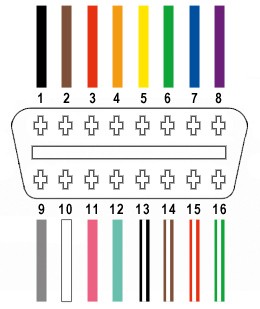
Out of the 16 pins on the OBD2 connector (OBD2C), only four are required for this adapter:
- OBD2 Pin 4 (Chassis Ground): Connects to the orange wire on the OBD2C.
- OBD2 Pin 6 (CAN High): Connects to the green wire on the OBD2C.
- OBD2 Pin 14 (CAN Low): Connects to the brown with a white stripe wire on the OBD2C.
- OBD2 Pin 16 (Battery Power): Connects to the green with a white stripe wire on the OBD2C.
Building the Adapter: Step-by-Step Instructions
- Prepare the OBD2 Cable: Remove the outer sheath and shielding from the OBD2 cable, separating the four necessary wires (orange, green, brown/white, green/white). Secure the remaining wires with a zip tie.
- Prepare the Wires for the DVI-D Connector: Strip approximately 3/8″ of insulation from each wire. If the wire gauge is smaller than the DVI-D pin connector, fold and twist the exposed wire to increase its thickness. Slide a rubber seal onto each wire.
- Connect the Wires to the DVI-D Pins: Insert the exposed wire into the front prongs of the DVI-D pin. Solder the wire to the pin for a secure connection. Alternatively, use a Molex crimping tool to crimp the prongs over the wire.
- Secure the Rubber Seals: Slide the rubber seal up to the back prongs of the DVI-D pin and crimp the prongs over the seal using pliers.
-
Twist the Wire Pairs: Pair and twist the following wires: orange (Pin 4) with green/white (Pin 16), and green (Pin 6) with brown/white (Pin 14).
-
Connect the Pins to the DVI-D Connector: Insert the pins into the 4-pin DVI-D connector in the following order:
- Pin 14 (brown/white) into slot A
- Pin 6 (green) into slot B
- Pin 16 (green/white) into slot C
- Pin 4 (orange) into slot D
- Test the Adapter: Connect the adapter to your vehicle’s OBD2 port and your diagnostic device. Verify functionality by checking and clearing error codes.
This completes the DVI-D to OBD2 adapter build. Remember, this project requires careful attention to detail. Double-check all connections before use.