The On-Board Diagnostics (OBD) port, specifically the OBD-II iteration found in most modern vehicles, serves as a crucial interface for accessing vehicle data. This data allows mechanics to diagnose issues, but also enables functionalities like vehicle tracking. This article delves into the specifics of the L-line Obd2 protocol, one of the communication standards utilized by the OBD-II system.
 OBD-II connector and pinouts
The evolution of automotive technology has led to sophisticated computer systems managing various vehicle functions. These systems rely on sensors and Electronic Control Units (ECUs) to monitor and control everything from engine emissions to anti-lock brakes. The OBD-II system, mandated in vehicles manufactured after 1996, provides a standardized way to access diagnostic information generated by these systems. This information is crucial for identifying malfunctions and ensuring efficient repairs. A key component of this system is the Data Link Connector (DLC), a 16-pin connector typically located under the dashboard. While primarily used for diagnostics, the OBD-II port also supports functionalities like vehicle tracking through GPS devices. However, the constant connection and disconnection of devices can expose the port to Electrostatic Discharge (ESD), potentially damaging sensitive electronics. Protecting the OBD-II port with Transient Voltage Suppression (TVS) diodes is essential to prevent such damage.
Decoding the OBD-II Pin Configuration and the Role of L-Line OBD2
The OBD-II DLC, also known as the J1962 connector, features a specific pin configuration where each pin serves a designated purpose. Pin 16 provides battery power, while pins 4 and 5 are grounded. Critical for communication are pins 6 and 14, dedicated to the CAN Bus (High and Low signals, respectively), and pins 2 and 10, utilizing the SAE J1850 protocol. Crucially, pins 7 and 15 employ the ISO9141 protocol, with pin 7 designated as the K-line and pin 15 as the L-line OBD2. The remaining pins are left unassigned for manufacturer-specific applications.
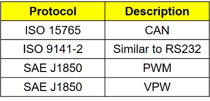
The OBD-II system supports several communication protocols, each favored by different manufacturers. These protocols include ISO 15765 (CAN), ISO 9141-2 (K-Line and L-Line), SAE J1850 PWM, and SAE J1850 VPW. Each protocol employs distinct signaling characteristics and data rates. For instance, ISO 15765 utilizes differential signaling on the CAN High and CAN Low lines with data rates up to 1Mbps. The L-line OBD2, part of the ISO 9141-2 protocol, operates at a lower data rate of 10.4Kbps and utilizes a single-wire communication method alongside the K-line for initialization and communication.
L-Line OBD2: A Critical Component in Vehicle Diagnostics
Understanding the specific role of the L-line OBD2 within the broader context of the OBD-II system is essential for effective vehicle diagnostics and utilizing functionalities like GPS tracking. Proper ESD protection for this and other critical pins ensures the integrity of the OBD-II system and the connected devices. This overview provides a foundation for understanding the intricacies of the OBD-II system and its communication protocols. Future articles will delve deeper into ESD protection strategies specific to each pin, including the l-line obd2, ensuring reliable and safe operation of diagnostic and tracking equipment.